This unit is really the start to our formal learning of digital electronics. The first two units were meant to get you familiar with various components and tools of digital electronics; now we get to start with the basics of the circuit design process and develop our own circuits. As we progress, we’ll follow the Circuit Design Process:
- Define the problem (inputs and outputs)
- Create the truth table
- Write the AOI logic expression
- Simplify the AOI logic expression if we can
- Draw the AOI circuit diagram
- Simulate in Multisim to test
- Build on the breadboard to test and confirm
This process is the process we’ll use throughout the year to design our own circuits. We’ll learn various tools to enhance the process and make some things happen quicker, but the basics of the process will remain the same. In this unit, you’ll work through the process in three main steps.
- STEP 1: Learn how to create truth tables from situations and how to write logic expressions
- STEP 2: Practice creating AOI circuit diagrams by hand and in Multisim
- STEP 3: Apply this knowledge in the solution to a voting problem
When you’re done, you’ll have a good understanding of the circuit design process and what needs to be done to design and build a working circuit as a solution to a real problem.
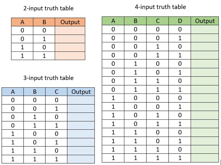
The first part of this unit focuses on understanding Truth Tables. Truth Tables are ways for us to formally organize the possible on/off (1/0) combinations of inputs and what that should translate into for outputs. The circuit design process starts with the development of a truth table because that will give us the organization we need to write a logic expression. As you work through this first part of the unit, most of the work will be hand-written as you convert truth tables into logic expressions and vice-versa.
GRADING & PROCESS
![]() Watch the Combinational Logic Overview and the Truth Tables to Logic Expressions presentations. Take a full page of notes on constructing truth tables and writing expressions from them.
Watch the Combinational Logic Overview and the Truth Tables to Logic Expressions presentations. Take a full page of notes on constructing truth tables and writing expressions from them.
![]() Complete the Truth Tables to Expressions Assignment.
Complete the Truth Tables to Expressions Assignment.
![]() Watch the presentation on Logic Analysis, taking careful notes on how to turn an AOI circuit into a truth table.
Watch the presentation on Logic Analysis, taking careful notes on how to turn an AOI circuit into a truth table.
![]() Complete the AOI Circuits to Truth Tables Assignment.
Complete the AOI Circuits to Truth Tables Assignment.
![]() Have Mr. Benshoof approve your notes and completed Assignments.
Have Mr. Benshoof approve your notes and completed Assignments.
Truth Tables to Logic Expressions
AOI Logic Analysis
AOI Overview
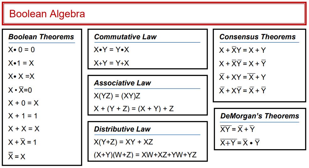
Boolean Algebra Equations
![]() Download the Part 2 Rubric Only
Download the Part 2 Rubric Only
![]() Take the Unit 2 Quiz
Take the Unit 2 Quiz
Our second part to the unit covers how to convert our logic expressions into actual circuit diagrams. To do this, we’ll emphasize on how mathematical notation for multiplying and adding turns into the “Ands” and “Ors” or AOI logic. We’ll also look at some Boolean Algebra rules that let us simplify logic expressions before making circuits.
GRADING & PROCESS
![]() Take a full page of good notes on AOI Implementation. Make sure to emphasize when each of the three gates (And/Or/Inverter) are used!
Take a full page of good notes on AOI Implementation. Make sure to emphasize when each of the three gates (And/Or/Inverter) are used!
![]() Complete the AOI Implementation Assignment.
Complete the AOI Implementation Assignment.
![]() Use Multisim to simulate and then breadboard the required circuits from the AOI Implementation Assignment.
Use Multisim to simulate and then breadboard the required circuits from the AOI Implementation Assignment.
![]() Take a full page of careful notes on Simplifying Expressions – be sure to emphasize the different rules for simplifying.
Take a full page of careful notes on Simplifying Expressions – be sure to emphasize the different rules for simplifying.
![]() Complete the Simplifying Expressions Assignment.
Complete the Simplifying Expressions Assignment.
![]() Take the Unit 2 Quiz: AOI Design!
Take the Unit 2 Quiz: AOI Design!
![]() Have Mr. Benshoof check-off your notes, assignments, and circuits.
Have Mr. Benshoof check-off your notes, assignments, and circuits.
AOI Implementation
Simplifying Expressions
Simplification Overview
Our unit ends with a short project that has you work through the entire circuit design process in the creation of a solution to a small problem. In this “Majority Vote” problem, you’ll be asked to create a circuit that can tally votes for a small group of people following a specific set of criteria. You’ll need to start by creating a truth table from the problem situation, then writing an AOI logic expression and simplifying if possible. You’ll then convert your expression into a hand-drawn circuit, a Multisim simulation, and finally a breadboarded model.
GRADING & PROCESS
![]() Read through the Majority Vote problem carefully and watch the overview video.
Read through the Majority Vote problem carefully and watch the overview video.
![]() Create a Truth Table that describes the situation in your engineering notebook.
Create a Truth Table that describes the situation in your engineering notebook.
![]() Write an unsimplified logic expression from your truth table.
Write an unsimplified logic expression from your truth table.
![]() Simplify your logic expression to get a final simplified logic expression.
Simplify your logic expression to get a final simplified logic expression.
![]() Have Mr. Benshoof confirm your simplified logic expression.
Have Mr. Benshoof confirm your simplified logic expression.
![]() Draw an AOI circuit diagram from your simplified logic expression
Draw an AOI circuit diagram from your simplified logic expression
![]() Simulate your AOI circuit in Multisim
Simulate your AOI circuit in Multisim
![]() Breadboard your AOI circuit and confirm that it works
Breadboard your AOI circuit and confirm that it works
![]() Have Mr. Benshoof confirm your working breadboard circuit.
Have Mr. Benshoof confirm your working breadboard circuit.
Part 1 Resources
Part 2 Resources
Part 3 Resources