Welcome to the 5th unit of Digital Electronics! By now, we’ve seen all the steps of the Circuit Design Process. Using this process it’s possible to turn real-world problems, questions, or scenarios into actual working digital circuits. Throughout the semester we’ve covered the different steps of the circuit design process, and they go like this:
- Define inputs & outputs
- Create a truth table
- Create an unsimplified logic expression
- Use Boolean algebra or a K-Map to simplify the expression
- Create an AOI circuit by hand
- Convert any parts of the circuit to NAND/NOR as needed
- Simulate in Multisim
- Add proper displays or display drivers
- Breadboard!
This process will all come together in this unit into one giant problem: The Birthday Problem. The completion of this circuit will give us a solid overview of the whole process, and also launch us into our next concept: the Programmable Logic Device (PLD). At the end of the unit, you will have reviewed and practiced the Circuit Design process in its entirety. You’ll also be ready for the next topic: PLDs.
The first part of this unit asks you to go back and review some of the key ideas from the semester. We’ll go back as far as AOI logic and NAND/NOR logic, as well as reviewing things like truth tables, K-Mapping, counting in binary, and even 7-segment displays. It’s important to revisit each of these ideas briefly before the full Birthday Problem because each of those steps in the circuit design process will play a major role in the success of next project. As you review these ideas, be sure to take a few pages of good notes as you think through those earlier topics from your new vantage point!
GRADING & PROCESS
![]() Think about the circuits you’ve designed and built this semester. Things like the Fireplace Circuit, Majority Vote, and Seatbelt Circuit. T ake a page of notes describing what you see as being the steps of the Circuit Design process. Make yourself a cool and complete graphic organizer that outlines the main steps!
Think about the circuits you’ve designed and built this semester. Things like the Fireplace Circuit, Majority Vote, and Seatbelt Circuit. T ake a page of notes describing what you see as being the steps of the Circuit Design process. Make yourself a cool and complete graphic organizer that outlines the main steps!
![]() Watch the four presentation on Displays, Binary, Truth tables, and the “Top Secret Pro Tool” (sshhh… don’t tell anyone!). Take a full page of notes on these ideas.
Watch the four presentation on Displays, Binary, Truth tables, and the “Top Secret Pro Tool” (sshhh… don’t tell anyone!). Take a full page of notes on these ideas.
![]() Watch the four presentation on K-Maps, AOI, NAND, and NOR. Take a full page of notes on these ideas.
Watch the four presentation on K-Maps, AOI, NAND, and NOR. Take a full page of notes on these ideas.
![]() Have Mr. Benshoof approve your notes.
Have Mr. Benshoof approve your notes.
Seven Segment Displays
Counting in Binary
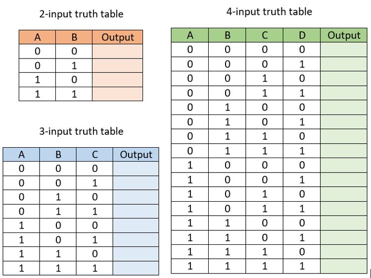
Truth Tables
(Top Secret Pro Tool)
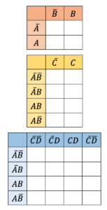
K-Mapping
AOI Circuit Design
NOR Logic
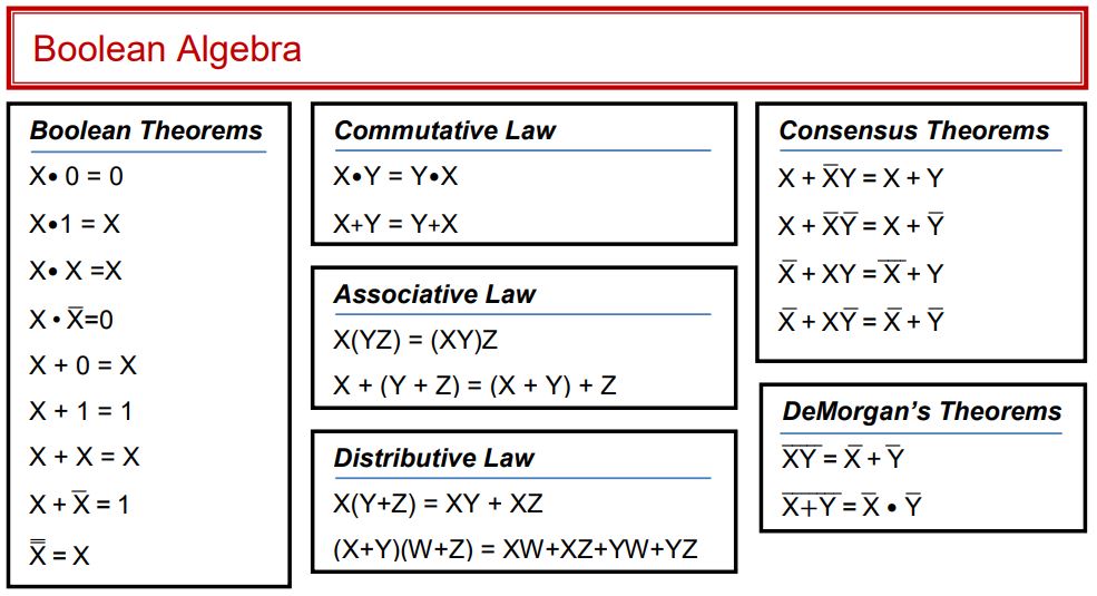
Boolean Algebra Equations
![]() Download the Part 2 Rubric Only
Download the Part 2 Rubric Only
![]() Take the Unit 2 Quiz
Take the Unit 2 Quiz
Our second part to the unit covers how to convert our logic expressions into actual circuit diagrams. To do this, we’ll emphasize on how mathematical notation for multiplying and adding turns into the “Ands” and “Ors” or AOI logic. We’ll also look at some Boolean Algebra rules that let us simplify logic expressions before making circuits.
GRADING & PROCESS
![]() Take a full page of good notes on AOI Implementation. Make sure to emphasize when each of the three gates (And/Or/Inverter) are used!
Take a full page of good notes on AOI Implementation. Make sure to emphasize when each of the three gates (And/Or/Inverter) are used!
![]() Complete the AOI Implementation Assignment.
Complete the AOI Implementation Assignment.
![]() Use Multisim to simulate and then breadboard the required circuits from the AOI Implementation Assignment.
Use Multisim to simulate and then breadboard the required circuits from the AOI Implementation Assignment.
![]() Take a full page of careful notes on Simplifying Expressions - be sure to emphasize the different rules for simplifying.
Take a full page of careful notes on Simplifying Expressions - be sure to emphasize the different rules for simplifying.
![]() Complete the Simplifying Expressions Assignment.
Complete the Simplifying Expressions Assignment.
![]() Take the Unit 2 Quiz: AOI Design!
Take the Unit 2 Quiz: AOI Design!
![]() Have Mr. Benshoof check-off your notes, assignments, and circuits.
Have Mr. Benshoof check-off your notes, assignments, and circuits.
AOI Implementation
Simplifying Expressions
Simplification Overview
Our unit ends with a short project that has you work through the entire circuit design process in the creation of a solution to a small problem. In this “Majority Vote” problem, you’ll be asked to create a circuit that can tally votes for a small group of people following a specific set of criteria. You’ll need to start by creating a truth table from the problem situation, then writing an AOI logic expression and simplifying if possible. You’ll then convert your expression into a hand-drawn circuit, a Multisim simulation, and finally a breadboarded model.
GRADING & PROCESS
![]() Read through the Majority Vote problem carefully and watch the overview video.
Read through the Majority Vote problem carefully and watch the overview video.
![]() Create a Truth Table that describes the situation in your engineering notebook.
Create a Truth Table that describes the situation in your engineering notebook.
![]() Write an unsimplified logic expression from your truth table.
Write an unsimplified logic expression from your truth table.
![]() Simplify your logic expression to get a final simplified logic expression.
Simplify your logic expression to get a final simplified logic expression.
![]() Have Mr. Benshoof confirm your simplified logic expression.
Have Mr. Benshoof confirm your simplified logic expression.
![]() Draw an AOI circuit diagram from your simplified logic expression
Draw an AOI circuit diagram from your simplified logic expression
![]() Simulate your AOI circuit in Multisim
Simulate your AOI circuit in Multisim
![]() Breadboard your AOI circuit and confirm that it works
Breadboard your AOI circuit and confirm that it works
![]() Have Mr. Benshoof confirm your working breadboard circuit.
Have Mr. Benshoof confirm your working breadboard circuit.
Part 1 Resources
Part 2 Resources
Part 3 Resources