Welcome to the 4th unit of Digital Electronics! By now we understand the basics of the circuit design process, it’s just time to add new tools to what we know. In this unit, we’ll get tools that let us display numbers and letters more easily, combine (or uncombine) digital signals, and perform basic mathematics using only digital circuits. As we progress, we’ll be thinking about the following questions:
- How can a digital (on/off) circuit display things like numbers and letters?
- How can we combine lots of individual signals into one larger digital signal?
- How could we break apart a large digital signal into multiple smaller ones?
- How do binary numbers work with negatives?
- How do we add binary numbers, and how can that be done with a digital circuit?
These questions will keep us moving forward through the unit as we learn more ways that circuits can be made to do complex things. For this unit, you’ll work through three main stages:
- STEP 1: Learn how to use 7-segment displays in your digital circuits
- STEP 2: Learn about multiplexers and demultiplexers
- STEP 3: Binary math through digital logic
At the end of the unit, you will have learned about new integrated circuit chips (IC chips) that can help make more complex digital signals. You’ll also learn how to make displays of numbers and letters, and how to build a basic calculator. Together, the circuits you build in this unit will help demonstrate the use of many new digital electronics tools.
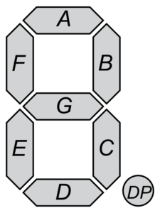
7-Segment Display Map
As we start our next unit, we’ll turn our attention to some new digital components. Here, we get to look at 7-Segment Displays and their Drivers. A 7-Segment Display takes seven inputs to turn on/off individual segments in what is basically a complicated LED. This system lets us show numbers and some letters as we build circuits that we want to be able to read. The Driver for these displays can take a 4-bit input (like the binary number 1100), and converts it into the seven on/off signals for the 7-Segment Display. In this part of the unit, you get to investigate how these work together to give us more functionality in our digital designs.
GRADING & PROCESS
![]() Watch the Displays Overview, 7-Segment Displays, and 7-Segment Display Driver videos and take a full page of notes.
Watch the Displays Overview, 7-Segment Displays, and 7-Segment Display Driver videos and take a full page of notes.
![]() Complete the investigation 7-Segment Displays Assignment.
Complete the investigation 7-Segment Displays Assignment.
![]() Create the given circuits in Multisim and by breadboarding to learn how the displays work and to answer the reflection questions.
Create the given circuits in Multisim and by breadboarding to learn how the displays work and to answer the reflection questions.
![]() Have Mr. Benshoof approve your notes and completed Assignments.
Have Mr. Benshoof approve your notes and completed Assignments.
Displays Overview
7-Segment Displays
Display Drivers
Often we have systems with a different number of inputs and outputs to work together correctly. One example is when we have a 4-bit binary input for a 7-seven segment display, but need the 7 individual inputs to make it work. In cases like this, we can use multiplexers & demultiplexers to change those digital signals and either combine them or break them apart. In this part of our unit, we’ll learn how to use multiplexers to combine multiple signals into just one. We’ll also learn how to use demultiplexers to take one large signal and break it apart into smaller ones.
GRADING & PROCESS
![]() Take a full page of careful notes on multiplexers and demultiplexers while watching our four presentations.
Take a full page of careful notes on multiplexers and demultiplexers while watching our four presentations.
![]() Use Multisim and your breadboard to build the circuits required for the Multiplexer/Demultiplexer Assignment.
Use Multisim and your breadboard to build the circuits required for the Multiplexer/Demultiplexer Assignment.
![]() Complete the Multiplexer/Demultiplexer Assignment.
Complete the Multiplexer/Demultiplexer Assignment.
![]() Have Mr. Benshoof check-off your notes, assignments, and circuits.
Have Mr. Benshoof check-off your notes, assignments, and circuits.
MUX/DEMUX Signals
Multiplexers
Demultiplexers
Binary Math Overview
The last part of our unit will ask us to tackle some tough mathematics and learn two new logic gates. The new math we’ll need to learn is called the “2’s Complement”, and it’s a way that binary numbers can represent negative numbers. This is particularly useful if we want to use an adding machine to do subtraction. After that, we’ll learn about the new logic gates XOR and XNOR, and then look at a circuit that can add binary numbers. As usual, we’ll simulate the circuit in Multisim and breadboard it so we can investigate how it works!
GRADING & PROCESS
![]() Take a full page of detailed notes on the 2’s Complement process. Two presentations are provided to give you multiple explanations of how this works.
Take a full page of detailed notes on the 2’s Complement process. Two presentations are provided to give you multiple explanations of how this works.
![]() Complete the 2’s Complement Assignment.
Complete the 2’s Complement Assignment.
![]() Take another page of notes, this time on the XOR and XNOR gates as well as the logic behind the Binary Adders circuit.
Take another page of notes, this time on the XOR and XNOR gates as well as the logic behind the Binary Adders circuit.
![]() Use Multisim to simulate the binary adders shown in the assignment.
Use Multisim to simulate the binary adders shown in the assignment.
![]() Complete the Binary Adders Assignment using your circuits.
Complete the Binary Adders Assignment using your circuits.
![]() Have Mr. Benshoof check-off your notes, assignments, and circuits.
Have Mr. Benshoof check-off your notes, assignments, and circuits.
2’s Complement Arithmetic
2’s Complement Arithmetic Again
XOR, XNOR & Binary Adders
Part 1 Resources
Part 2 Resources